VALVE ACTUATORS PROVIDE ADVANCED PREDICTIVE MAINTENANCE CAPABILITIES
Description
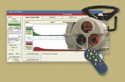
Rotork IQ Pro electric, non-intrusive valve actuators include a powerful data-logging feature that monitors valve performance, so users can forecast when valve maintenance might be required and manage assets for maximum productivity.
The IQ Pro stores historical and current operating data, including valve torque profiles, number of operations, valve and actuator positions, and other vital performance and operational statistics.
Users can download the data by pointing an intrinsically safe Rotork IQ Pro setting tool at the actuator. The information is downloaded wirelessly and stored in the setting tool in seconds. Then, users can upload the data to virtually any laptop PC or desktop computer. Rotork provides software for a feature-rich, user-friendly interface, so asset analysis and creating reports is fast and easy.
Rotork IQ Pro actuators are non-intrusive, rugged, and reliable. They are used in a wide range of water and wastewater treatment; electric power generation; oil and gas; pulp and paper; hydrocarbon processing; chemical manufacturing; and many other applications all over the globe. Rotork IQ Pro actuators integrate easily with most SCADA, PLC, and DCS networks.
concont
Specs
• General specification for electric actuators – Integral motor control • 1 General • The actuators shall be suitable for use on a nominal _volt _ phase Hz power supply and are to incorporate motor, integral reversing starter, local control facilities and terminals for remote control and indication connections housed within a self contained, sealed enclosure. • In order to maintain the integrity of the enclosure, setting of the torque levels, position limits and configuration of the indication contacts etc shall be carried out without the removal of any actuator covers over an Infra red interface. Sufficient commissioning tools shall be provided with the actuators and must meet the enclosure protection and certification levels of the actuators. Commissioning tools shall not form an integral part of the actuator and must be removable for secure storage/authorised release. In addition, provision shall be made for the protection of configured actuator settings by a means independent of access to the commissioning tool. • The actuator shall include a device to ensure that the motor runs with the correct rotation for the required direction of valve travel irrespective of the connection sequence of the power supply. • 2 Actuator sizing • The actuator shall be sized to guarantee valve closure at the specified differential pressure and temperature. The safety margin of motor power available for seating and unseating the valve shall be sufficient to ensure torque switch trip at maximum valve torque with the supply voltage 10% below nominal. For linear operating valves, the operating speed shall be such as to give valve closing and opening at approximately 10-12 inches per minute unless otherwise stated in the data sheet. For 90 valve types the operating time will be specified. • 3 Environmental • Actuators shall be suitable for indoor and outdoor use. The actuator shall be capable of functioning in an ambient temperature ranging from -33°C(22°F) to 70°C( 140°F), up to 100% relative humidity. • Actuators for hazardous area applications shall meet the area classification, gas group and surface temperature requirements specified in data sheet. • 4 Enclosure • Actuators shall be 0-ring sealed, watertight to /IP68 7m for 72hrs, NEMA 4, 6. The motor and all other internal electrical elements of the actuator shall be protected from ingress of moisture and dust when the terminal cover is removed for site for cabling, the terminal compartment having the same ingress protection rating as the actuator with the terminal cover removed. • Enclosure must allow for temporary site storage without the need for electrical supply connection. • All external fasteners shall be zinc plated stainless steel. The use of unplated stainless steel or steel fasteners is not permitted. • 5 Motor • The motor shall an integral part of the actuator, designed specifically for valve actuator applications. It shall be a low inertia high torque design, class F insulated with a class B temperature rise giving a time rating of 15 minutes at 40°C(104°F) at an average load of at least 33% of maximum valve torque. Temperature shall be limited by thermostats embedded in the motor end windings and integrated into its control. • Electrical and mechanical disconnection of the motor should be possible without draining the lubricant from the actuator gearcase. • 6 Motor protection • Protection shall be provided for the motor as follows: • Stall - the motor shall be de-energized within 8 seconds in the event of a stall when attempting to unseat a jammed valve. • Over temperature - thermostat will cause tripping of the motor. Auto-reset on cooling • Single phasing - lost phase protection. • Direction – phase rotation correction. • 7 Gearing • The actuator gearing shall be totally enclosed in a oil-filled gearcase suitable for operation at any angle. Grease lubrication is not permissible. All drive gearing and components must be of metal construction and incorporate a lost-motion hammerblow feature. For rising spindle valves the output shaft shall be hollow to accept a rising stem, and incorporate thrust bearings of the ball or roller type at the base of the actuator. The design should be such as to permit the opening of the gearcase for inspection or disassembled without releasing the stem thrust or taking the valve out of service. For 90 operating type of valves drive gearing shall be self locking to prevent the valve backdriving the actuator. • 8 Hand operation • A handwheel shall be provided for emergency operation, engaged when the motor is declutched by a lever or similar means, the drive being restored to power automatically by starting the motor. The handwheel or selection lever shall not move on restoration of motor drive. Provision shall be made for the hand/auto selection lever to be locked in both hand and auto positions. It should be possible to select hand operation while the actuator is running or start the actuator motor while the hand/auto selection lever is locked in hand without damage to the drive train. • Clockwise operation of the handwheel shall give closing movement of the valve unless otherwise stated in the data sheet. For linear valve types the actuator handwheel drive must be mechanically independent of the motor drive and should be such as to permit valve operation in a reasonable time with a manual force not exceeding 400N through stroke and 800N for seating/unseating of the valve. • 9 Drive bushing • The actuator shall be furnished with a drive bushing easily detachable for machining to suit the valve stem or gearbox. input shaft. Normally the drive bush shall be positioned in a detachable base of the actuator. Thrust bearings, when housed in a separate thrust base should be of the sealed for life type. • 10 Torque and turns limitation • Torque and turns limitation to be adjustable as follows: • Position setting range – multi-turn: 2.5 to 100,000 turns, with resolution to 15 deg. of actuator output. • Position setting range – direct drive part turn actuators: 90 +/-10, with resolution to 0.1 deg. of actuator output. • Torque setting: 40% to 100% rated torque. • . • Measurement of torque shall be from direct measurement of force at the output of the actuator. Methods of determining torque-using data derived from the motor such as motor speed, current, flux etc are not acceptable • A means for automatic “torque switch bypass” to inhibit torque off during valve unseating and “latching” to prevent torque switch hammer under maintained or repeated control signals shall be provided. • The electrical circuit diagram of the actuator should not vary with valve type remaining identical regardless of whether the valve is to open or close on torque or position limit. • 11 Remote valve position/actuator status indication. • Four contacts shall be provided which can be selected to indicate any position of the valve, Provision shall be made for the selection of a normally closed or open contact form. Contacts shall maintain and update position indication during handwheel operation when all external power to the actuator is isolated. • The contacts shall be rated at 5A, 250V AC, 30V DC. • As an alternative to providing valve position any of the four above contacts shall be selectable to signal one of the following: • Valve opening, closing or moving • Thermostat tripped, lost phase • Motor tripped on torque in mid travel, motor stalled • Remote selected • Actuator being operated by handwheel • Provision shall be made in the design for an additional 4 contacts having the same functionality. • Provision shall be made in the design for the addition of a contactless transmitter to give a 4-20mA analogue signal corresponding to valve travel for remote indication when required. The transmitter will auto range to the set limits • 12 Local position indication • The actuator display shall include a dedicated numeric/symbol digital position indicator displaying valve position from fully open to fully closed in 1% increments. Valve closed and open positions shall be indicated by symbols showing valve position in relation to the pipework to ensure that valve status is clearly interpreted. With main power on the display shall be backlit to enhance contrast at low light levels and shall be legible from a distance of at least 6 feet (2m). • Red, green, and yellow lights corresponding to open, closed, and intermediate valve positions shall be included on the actuator display when power is switched on. The digital display shall be maintained and updated during handwheel operation when all power to the actuator is isolated. • In addition, the actuator display shall include a separate text display element with a minimum of 32 characters to display operational, alarm and configuration status.. The text display shall be selectable between English and one of the following languages: Spanish, German, French, Italian, and Portuguese. Provision shall be made to upload a different language without removal of any covers or using specialized tools not provided as standard with the actuator. • Provision shall be made to orientate the actuator display through increments of 90. • 13 Local torque Indication: • The digital display shall be capable of indicating real time torque and valve position simultaneously, both being displayed in 1% increments of valve position and actuator rated torque. In addition torque shall also be displayed in horizontal bar graph form. • 14 Integral starter and transformer • The reversing starter, control transformer and local controls shall be integral with the valve actuator suitably housed to prevent breathing and condensation. The starter shall be suitable for 60 starts per hour and of rating appropriate to motor size. The controls supply transformer shall be fed from two of the incoming three phases and incorporate overload protection. It shall have the necessary tappings and be adequately rated to provide power for the following functions: • Energization of the contactor coils. • 24V DC output for remote controls. • Supply for all the internal electrical circuits. • 15 Local controls • The actuator shall incorporate local controls for Open, Close and Stop and a Local/Stop/Remote mode selector switch lockable in any one of the following three positions: local control only, stop (no electrical operation), remote control plus local stop only. It shall be possible to select maintained or non-maintained local control. • The local controls shall be arranged so that the direction of valve travel can be reversed without the necessity of stopping the actuator. • Provision shall be made to orientate the local controls through increments of 90. • 16 Control facilities • The necessary control, wiring and terminals shall be provided in the actuator for the following functions: • Open and close external interlocks to inhibit local and remote valve opening and/or closing control. It shall be possible to configure the interlocks to be active in remote control only. • Remote controls fed from an internal 24V DC supply and/or from an external supply between 20V and 120V AC or 20V and 60 V DC, to be suitable for any one or more of the following methods of control: • Open, Close and Stop control. • Open and Close maintained or “push to run” (inching) control. • Overriding Emergency Shut-down to Close (or Open) valve from a normally closed or open contact. • Two-wire control, energise to close (or open), de-energise to open (or close). • It shall be possible to reverse valve travel without the necessity of stopping the actuator. The motor starter shall be protected from excessive current surges during rapid travel reversal. • The internal circuits associated with the remote control and monitoring functions are to be designed to withstand • simulated lightning impulses of up to 2kV. • Provision shall be made for operation by distributed control system utilising the following network systems. • Modbus • Profibus • Foundation Fieldbus • DeviceNet • Pakscan • 17 Monitoring facilities • Facilities shall be provided for monitoring actuator operation and availability as follows: • Monitor (availability) relay, having one change-over contact, the relay being energized from the control transformer will de-energise under any one or more the following conditions: • Loss of main or customer 24V DC power supply • Actuator control selected to local or stop • Motor thermostat tripped • Actuator internal fault • Where specified, provision shall be made for contacts to provide discreet indication of one or more of the following: • Remote selected • Thermostat trip • Actuator fault • Actuator text display indication of the following status/alarms: • Closed Limit, open limit, moving open, moving closed, stopped • Torque trip closing, torque trip opening, stalled • ESD active, interlock active • Thermostat trip, phase lost, 24V supply lost, Local control failure • Configuration error, Position sensor failure, Torque sensor failure • Battery low, power loss inhibit • Integral datalogger to record and store the following operational data: • Opening last /average torque against position • Closing last /average torque against position • Opening motor starts against position • Closing motor starts against position • Total open/closed operations • Maximum recorded opening and closing torque values • Event recorder logging operational conditions (valve, control and actuator) • The datalogger shall record relevant time and date information for stored data. • Datalogger data is to be accessed via non-intrusive IrDA communication. Sufficient standard intrinsically safe tools shall be provided for downloading datalogger and actuator configuration files from the actuators and subsequent uploading to a PC. The actuator manufacturer shall supply PC software to enable datalogger files to be viewed and analysed. • 18 Wiring and terminals • Internal wiring shall be tropical grade PVC insulated stranded cable of appropriate size for the control and 3- • phase power. Each wire shall be clearly identified at each end. • The terminals shall be embedded in a terminal block of high tracking resistance compound. • The terminal compartment shall be separated from the inner electrical components of the actuator by means of a • watertight seal and shall be provided with a minimum of 2 threaded cable entries with provision for a maximum of 4. • All wiring supplied as part of the actuator to be contained within the main enclosure for physical and environmental • protection. External conduit connections between components are not acceptable. • A durable terminal identification card showing plan of terminals shall be provided attached to the inside of the terminal box cover indicating: • Serial number • External voltage values • Wiring diagram number • Terminal layout • The code card shall be suitable for the contractor to inscribe cable core identification alongside terminal numbers. • 19 Start-up kit • Each actuator shall be supplied with a start-up kit comprising installation instruction manual, electrical wiring diagram and cover seals to make good any site losses during the commissioning period. In addition, sufficient actuator commissioning tools shall be supplied to enable actuator set up and adjustment during valve/actuator testing and site installation commissioning. • 20 Performance test certificate • Each actuator must be performance tested and individual test certificates shall be supplied free of charge. The test • equipment should simulate a typical valve load, and the following parameters should be recorded. • Current at maximum torque setting • Torque at max. torque setting • Flash test voltage • Actuator output speed or operating time. •